USB, which stands for Universal Serial Bus, is a universal interface standard used to connect various external devices to computers. USB interfaces are often integrated into PCBs (Printed Circuit Boards) to enable data transfer and power supply between devices and computers. Here is an introduction to implementing a USB interface on a PCB:
- USB Types: USB standards come in multiple versions such as USB 1.1, USB 2.0, USB 3.0, USB 3.1, and USB 3.2, each with different data transfer speeds and features. When implementing a USB interface on a PCB, you need to select the USB type that suits your application.
- USB Connectors: PCB USB interfaces typically include one or more USB connectors for inserting USB devices. USB connectors come in different types like Type-A, Type-B, Micro-USB, and USB-C, depending on the design requirements of the PCB and the type of connecting devices.
- Circuit Layout: USB interfaces on the PCB need to be connected to the computer or host. As a result, the USB interface must be connected to other components on the main circuit board, such as USB controllers and power management circuits. This requires careful design and layout to ensure signal integrity and stable power supply.
- Signal Transmission: USB interfaces use different conductors to transmit data, power, and ground signals. The PCB must incorporate these signal lines to ensure that devices can communicate and receive power correctly.
- USB Standard Symbols: On the PCB, USB interfaces are often accompanied by USB standard symbols or labels to indicate the type and function of the interface. These markings help users identify USB interfaces and determine their purpose.
- Power Management: USB interfaces are typically used to provide power to external devices. Therefore, the PCB needs appropriate power management circuits to ensure a stable power output and comply with USB standard current specifications.
- ESD Protection: Electrostatic discharge (ESD) is a potential issue that can damage USB interfaces and connected devices. Consequently, PCBs typically include ESD protection components to safeguard USB interfaces from the effects of ESD events.
- Packaging and Physical Layout: USB interfaces on PCBs need suitable packaging and physical layouts to ensure that they are easily accessible and can be connected to external devices.
USB interfaces are widely used in modern electronic devices, allowing for the connection of various devices like mice, keyboards, printers, storage devices, cameras, smartphones, and more. In PCB design, integrating and laying out USB interfaces sensibly is crucial to ensure the stability and performance of the devices.
USB 3.0 is a USB specification, which was initiated by Intel and other companies. It has been renamed as USB 3.1 Gen 1 by USB IF.
USB 2.0 has been widely recognized by PC manufacturers, and the interface has become a necessary interface for hardware manufacturers.
The maximum transmission bandwidth of USB2.0 is 480mbps (60MB / s), while that of USB3.0 is as high as 5.0gbps (500MB / s).
Please note that 5GB / s bandwidth is not 625mb / s obtained by dividing 5GB / s by 8. Instead, it adopts the same 10 bit transmission mode as SATA (a pair of error correction codes are added on the basis of USB2.0), so its full speed is only 500MB / s.
However, we should note that this is the theoretical transmission value. If several devices share a USB channel, the main control chip will allocate and control the bandwidth available to each device. For example, in USB1.1, all devices can only share 1.5mb/s bandwidth. If a single device takes up all the bandwidth of USB interface, it will bring difficulties to other devices.
working principle:
The reason why USB 3.0 has the performance of “speeding” is entirely due to the improvement of technology.
Compared with USB 2.0 interface, USB 3.0 adds more physical buses in parallel mode.
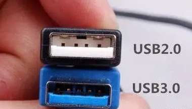
You can pick up a USB cable and look at the interface.
On the basis of the original 4-wire structure (power supply, ground wire, 2 pieces of data), USB 3.0 adds 4 lines for receiving and transmitting signals.
So there are eight lines in the cable and on the interface.
It is the additional 4 (2 pairs) of lines that provide the bandwidth required for “superspeed USB” to achieve “over speed”.
Obviously, two (1 pair) lines on USB 2.0 are not enough.
In addition, in the signal transmission method, the host control mode is still used, but the asynchronous transmission is changed.
USB 3.0 makes use of two-way data transmission mode instead of half duplex mode in USB 2.0 era. In short, data only needs to flow in one direction, which simplifies the time consumption caused by waiting.
In fact, USB 3.0 does not take any rarely heard of advanced technology, but theoretically increases the bandwidth by 10 times. As a result, it is more friendly and friendly. Once superspeed USB products come out, more people can easily accept and make better customized products.
Find out about our more info, Please contact us at service@pcbsky.com


