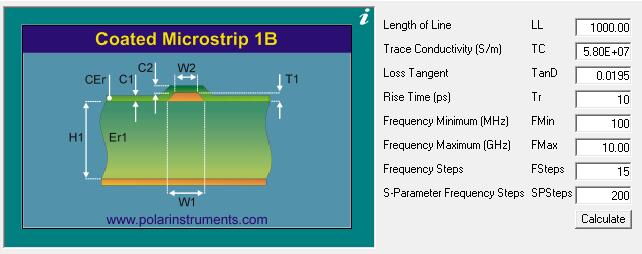
In today’s electronics industry, Printed Circuit Boards (PCBs) have become a critical component of nearly all electronic devices. For many high-frequency, high-speed, or precision applications such as communication equipment, medical instruments, and military systems, impedance control on the PCB has become paramount. Impedance control involves ensuring that signal transmission on the circuit board stays within design specifications to maintain signal integrity and performance stability.
To successfully achieve impedance control, selecting the right PCB manufacturer is crucial. In this article, we will explore how to choose the appropriate PCB manufacturer for impedance-sensitive designs to ensure that your circuit boards meet the requirements of your project.

Assessing PCB Manufacturers’ Expertise in Impedance Control
When embarking on a quest to find the ideal PCB manufacturer for your impedance-sensitive design, it’s crucial to evaluate their expertise. Impedance control demands a deep understanding of the intricacies involved in high-frequency circuitry. A manufacturer with a track record of successfully navigating these challenges will bring invaluable insights to your project.
Why Industry-Specific Experience Matters in Impedance-Sensitive PCBs
Experience in your industry matters. Different sectors have unique impedance requirements. A manufacturer familiar with your industry’s standards and challenges is better equipped to tailor solutions that precisely match your impedance needs.
The Role of Manufacturer Expertise in Achieving Impedance Precision
Expertise isn’t just a bonus; it’s the cornerstone of impedance precision. Experienced manufacturers have honed their techniques, allowing them to consistently produce PCBs that meet or exceed impedance specifications.
The Significance of Cutting-Edge Equipment in Impedance Control
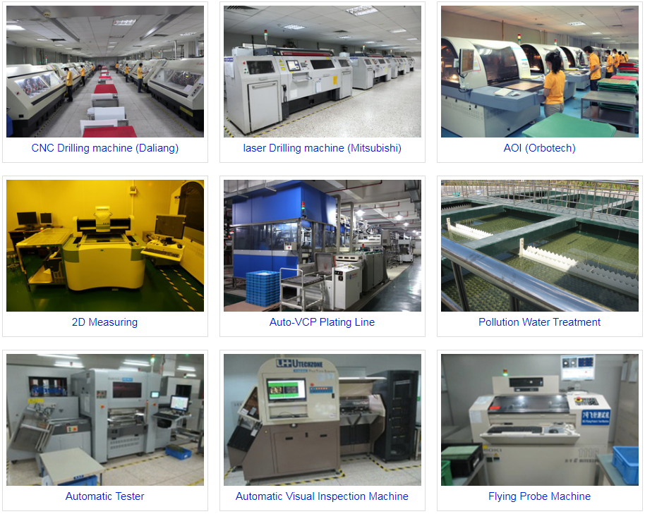
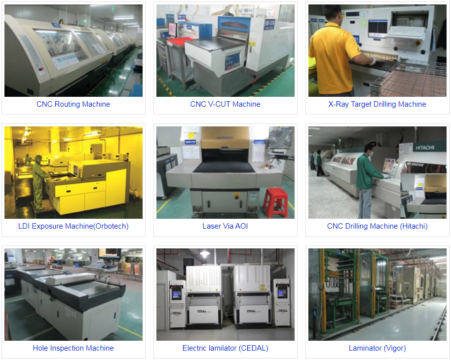
In the fast-paced world of electronics, technology evolves rapidly. Manufacturers equipped with the latest machinery and processes can offer superior impedance control. Cutting-edge equipment ensures that your PCBs are manufactured with the utmost precision.
Exploring Modern PCB Manufacturing Technologies for Impedance Optimization
Understanding the manufacturing technologies a company employs is essential. Techniques like controlled impedance routing and specialized substrate materials are vital for achieving impedance goals. A manufacturer’s commitment to staying up-to-date with these technologies is a strong indicator of their ability to deliver.
How Technology Choices Impact Impedance Performance
The choices a manufacturer makes regarding their technology stack have a direct impact on impedance performance. Ask potential partners about their technology choices and how they align with your impedance control requirements.
Ensuring Impedance Accuracy: The Importance of Quality Control
Quality control is the backbone of impedance accuracy. Manufacturers with stringent quality control procedures in place ensure that each PCB leaving their facility meets your impedance requirements. This meticulous process minimizes the risk of impedance deviations.
The Step-by-Step Guide to Quality Control for Impedance-Sensitive PCBs
Understanding a manufacturer’s quality control process is vital. A comprehensive quality control process should encompass impedance measurement, material inspection, and thorough testing, guaranteeing that your PCBs perform as expected.
How Stringent Quality Control Safeguards Your Impedance Requirements
Stringent quality control safeguards your project from impedance-related setbacks. It ensures that every PCB in your production run maintains the precise impedance levels your design demands.
Selecting the Right Materials for Impedance Matching in PCB Design
Materials play a pivotal role in impedance control. The selection of substrates and dielectric materials influences impedance characteristics significantly. Manufacturers well-versed in material science can guide you in choosing the right components for your design.
Balancing Layer Stackups for Precise Impedance Control
Layer stackups are another critical aspect of impedance-sensitive PCBs. Manufacturers skilled in optimizing stackups can help you strike the right balance between layer count and impedance control, ensuring your design goals are met.
Optimizing Impedance Through Material and Layer Choices
The interplay between materials and layer stackups is where impedance optimization truly shines. Collaborate closely with your chosen manufacturer to make informed decisions that maximize impedance performance.
Tailoring Impedance Solutions: The Customization Spectrum of PCB Manufacturers
Not all impedance requirements are the same. Customization is often necessary to achieve precise impedance matching. Seek out manufacturers with a spectrum of customization options, allowing you to fine-tune your PCBs to perfection.
Understanding the Benefits of Custom Impedance Solutions for Your Design
Customization isn’t just about meeting specifications; it’s about elevating performance. Explore the benefits of custom impedance solutions, from minimizing signal loss to enhancing overall circuit performance.
How Customization Enhances Impedance Matching Accuracy
Customization empowers you to achieve the highest levels of accuracy in impedance matching. By tailoring your PCB to your specific requirements, you can ensure that your design operates flawlessly.
The Collaborative Process: Working Closely with PCB Manufacturers on Impedance
Effective collaboration with your chosen PCB manufacturer is paramount to impedance success. It’s not just about handing off a design; it’s about working together to refine and optimize impedance control throughout the manufacturing process.
Effective Communication: Key to Achieving Impedance Goals
Clear and open communication is the linchpin of impedance control. Establish a robust communication channel with your manufacturer to address any concerns, changes, or challenges promptly.
Why Collaboration is the Cornerstone of Successful Impedance-Sensitive PCB Manufacturing
In the world of impedance-sensitive PCBs, collaboration isn’t an option; it’s a necessity. When you and your manufacturer collaborate effectively, you maximize your chances of achieving impedance-sensitive design success.
By considering these factors and engaging in a collaborative partnership with a PCB manufacturer that aligns with your impedance control needs, you can ensure that your electronic designs meet the highest standards of signal integrity and performance stability. Impedance control will no longer be a challenge but a well-executed element of your PCB manufacturing process.
PCBSky is a impedance PCB manufacturer from China, contact us for more info.

