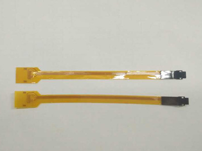
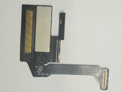
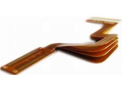
Single-sided flexible PCBs (Printed Circuit Boards) are a type of flexible electronic circuit board that has conductive traces and components on only one side. Unlike traditional rigid PCBs, flexible PCBs are made from flexible materials like polyimide or polyester, which allows them to bend and conform to different shapes and applications. Here are some key aspects of single-sided flexible PCBs:
- Flexible Substrate: Single-sided flexible PCBs are typically constructed using a flexible substrate material, such as polyimide (often referred to as “flex”), which can bend and twist without breaking the conductive traces.
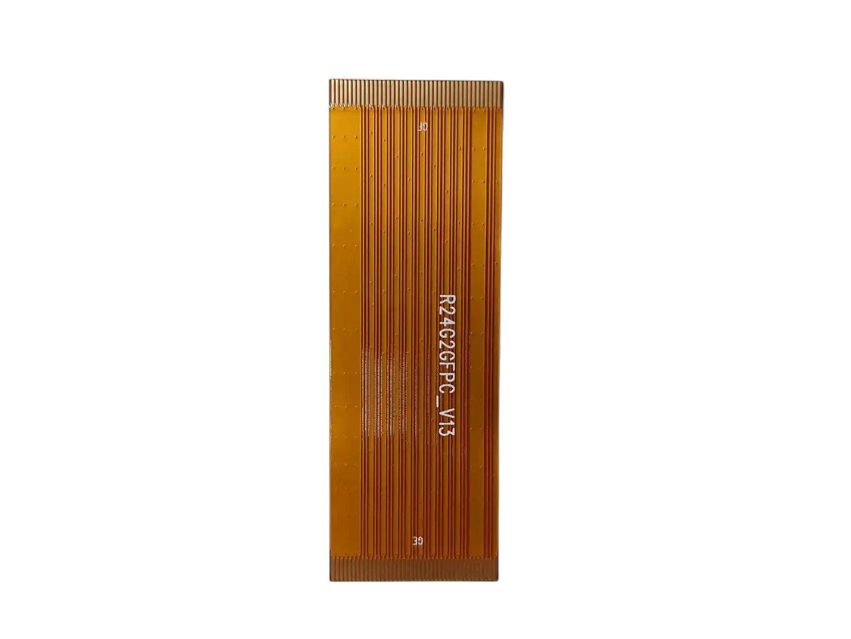
- Conductive Traces: The conductive traces are usually made of copper and are patterned on one side of the flexible substrate. These traces provide the electrical connections between various components, such as integrated circuits, resistors, and capacitors.
- Components: Electronic components can be mounted on the single-sided flexible PCB using various methods, including surface-mount technology (SMT) and through-hole technology (THT). The choice of components depends on the specific application and design requirements.
- Applications: Single-sided flexible PCBs are commonly used in applications where space is limited or where the circuit board needs to conform to a curved or irregular shape. Some common applications include:
- Wearable Electronics: Flexible PCBs are often used in smartwatches, fitness trackers, and other wearable devices where flexibility is crucial for comfort and form factor.
- Medical Devices: Medical devices, such as flexible catheters and sensors, often incorporate single-sided flexible PCBs to enable conformability and reduce the risk of damage during use.
- Automotive: Flexible PCBs can be found in automotive applications, including in-dash displays, interior lighting, and sensors where flexibility is beneficial.
- Aerospace: In aerospace applications, flexible PCBs can be used in satellites, aircraft, and drones to save weight and fit into tight spaces.
- Consumer Electronics: Some consumer electronics, like digital cameras and foldable smartphones, use single-sided flexible PCBs to accommodate unique form factors.
- Manufacturing Process: The manufacturing process for single-sided flexible PCBs involves etching the conductive traces onto the flexible substrate, adding components, and applying a protective cover layer to insulate the traces. The flexibility of the PCB depends on the choice of materials and the design.
- Advantages: Single-sided flexible PCBs offer several advantages, including reduced weight, flexibility, and the ability to fit into tight spaces. They can also reduce the need for bulky connectors and wiring harnesses.
- Challenges: Designing and manufacturing flexible PCBs can be more complex than rigid PCBs, and they may have limitations in terms of the number of layers and the complexity of the circuits that can be implemented.
In summary, single-sided flexible PCBs are a versatile solution for various applications where flexibility and space constraints are critical design factors. They offer the ability to create electronic circuits that conform to unique shapes and are commonly used in industries like electronics, healthcare, automotive, and aerospace.
The production process of single-sided Flexible PCB:
The production process of single-sided flexible PCBs (Printed Circuit Boards) involves several steps, from design and material selection to fabrication and assembly. Here’s an overview of the typical production process for single-sided flexible PCBs:
- Design and Layout:
- Design Specification: Define the electrical and mechanical requirements of the PCB, including the dimensions, component placement, and electrical connections.
- Schematic Design: Create a schematic diagram of the circuit, specifying the components and their connections.
- PCB Layout: Use PCB design software to create the layout of the single-sided flexible PCB, including the placement of components and the routing of conductive traces.
- Material Selection:
- Flexible Substrate: Choose a flexible substrate material, typically polyimide (PI) or polyester (PET). The choice of material depends on factors like temperature tolerance, flexibility, and cost.
- Copper Foil: Select the thickness and type of copper foil to be used for the conductive traces. Copper is commonly used due to its excellent electrical conductivity.
- Preparation of Flexible Substrate:
- Cleaning and Pre-treatment: The flexible substrate material is cleaned and pre-treated to improve adhesion and ensure that it is free of contaminants.
- Copper Cladding:
- Copper Foil Lamination: The selected copper foil is laminated onto one side of the flexible substrate using an adhesive layer. This creates the conductive layer.
- Circuit Patterning:
- Photoresist Application: A layer of photosensitive material (photoresist) is applied to the copper-clad side of the flexible substrate.
- Exposure: The PCB layout is printed onto the photoresist using a mask and UV light, exposing the areas where the copper will be etched away.
- Etching:
- Chemical Etching: The exposed copper is chemically etched away using an etching solution, leaving behind the desired conductive traces.
- Resist Stripping: The remaining photoresist is removed, leaving the conductive traces exposed.
- Component Placement:
- Surface Mount Technology (SMT): Surface-mount components are placed onto the PCB using automated pick-and-place machines. These components are attached to the conductive traces using solder paste.
- Through-Hole Technology (THT): Through-hole components are manually or automatically inserted through pre-drilled holes in the PCB and soldered on the opposite side.
- Soldering:
- Reflow Soldering: In the case of SMT components, the entire PCB is passed through a reflow soldering oven to melt the solder paste and create secure electrical connections.
- Hand Soldering: For THT components, manual soldering may be necessary.
- Insulation Layer:
- Cover Layer Application: An insulating cover layer (usually made of polyimide) is applied over the entire PCB to protect the conductive traces and components. This layer may also have openings to expose specific areas or components.
- Testing and Inspection:
- The completed single-sided flexible PCB undergoes electrical testing to ensure that all connections are functioning correctly.
- Visual inspection is conducted to check for any defects, such as solder bridges or component misalignment.
- Cutting and Forming:
- The single-sided flexible PCB may be cut and formed into its final shape, depending on the application. This step is crucial for ensuring that the PCB can conform to the desired shape or fit into the intended enclosure.
- Final Testing:
- The PCB is tested once again after cutting and forming to verify that it still functions correctly in its final shape.
- Packaging and Shipping:
- The finished single-sided flexible PCBs are packaged and prepared for shipping to the customer or for use in further assembly.
The specific details of the production process may vary depending on the manufacturer, the complexity of the PCB design, and the equipment used. However, these general steps provide an overview of the typical process involved in producing single-sided flexible PCBs.
Similarities and differences between Flexible Printed Circuit and Flat Flexible Cable
FPC (Flexible Printed Circuit) and FFC (Flat Flexible Cable) are both flexible circuitry used for connecting various components and transmitting electrical signals within electronic devices. They share some similarities but also have differences. Here are their similarities and differences:
Similarities:
- Flexibility: Both FPC and FFC exhibit flexible and bendable characteristics, making them suitable for adapting to various shapes and applications. They are used in situations where bending or curving connections are required.
- Conductivity: Both FPC and FFC contain conductive circuits for transmitting electrical signals and power. These circuits are typically made of copper foil or other conductive materials.
- Lightweight: Due to their flexible materials, both FPC and FFC are relatively lightweight and are suitable for applications with weight constraints, such as portable devices and aerospace applications.
- High-Density Connections: FPC and FFC can both support high-density connections because their circuits can be very fine, accommodating a large number of connections.
Differences:
- Structural Differences:
- FPC (Flexible Printed Circuit): FPCs typically have the overall structure of a flexible circuit board, resembling the appearance of traditional rigid PCBs but using a flexible substrate. They often have conductive traces, cover layers, and through-holes.
- FFC (Flat Flexible Cable): FFCs are usually flat cables with parallel-arranged conductors and do not have the integrated circuit board structure seen in FPCs. FFCs are primarily used for interconnecting components within electronic devices.
- Different Applications:
- FPC: FPCs are commonly used in applications that require a flexible circuit board to connect internal or external components, such as in smartphones, camera modules, LCD panel connections, etc.
- FFC: FFCs are typically used to connect internal components of electronic devices, such as connecting printheads to motherboards, linking LCD panels to driver circuits, and similar internal connections.
- Connection Methods:
- FPC: FPCs are usually connected to electronic devices via connectors or sockets, as they have an integrated circuit board structure.
- FFC: FFCs are often connected through methods like pressure connectors (pressure or ZIF connections) to the target device, often designed for one-time connections.
- Appearance Differences:
- FPC: FPCs look more like traditional circuit boards, often having a multi-layered structure with through-holes.
- FFC: FFCs resemble flat, ribbon-like cables with conductors arranged in parallel, and they typically do not have cover layers between the conductors.
In summary, FPC and FFC are both variations of flexible circuits used for different types of applications. The choice between them depends on the specific requirements of the application, including connection methods, appearance, structure, and circuit layout.
Welcome to custom Single Sided Printed Circuit Board directly from PCB Manufacturer at low cost.
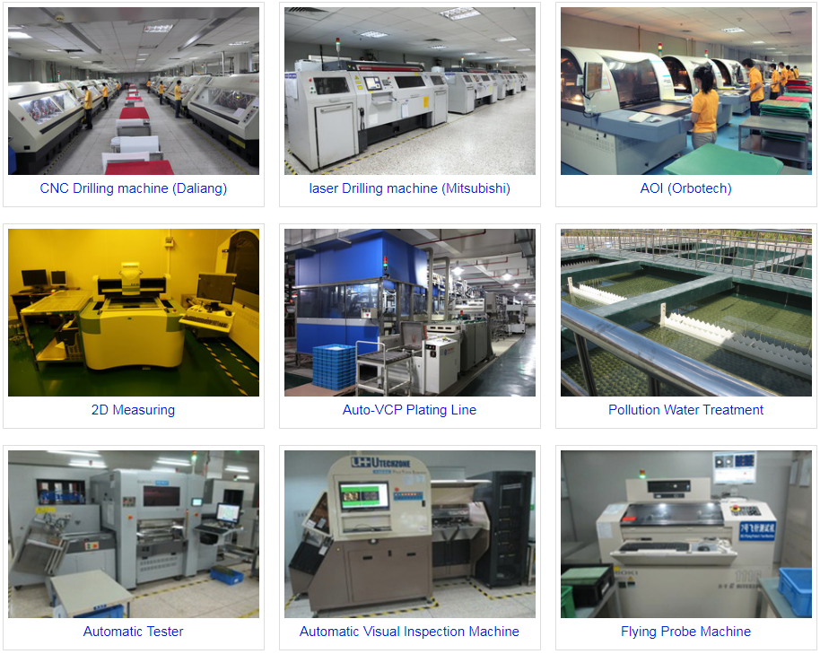
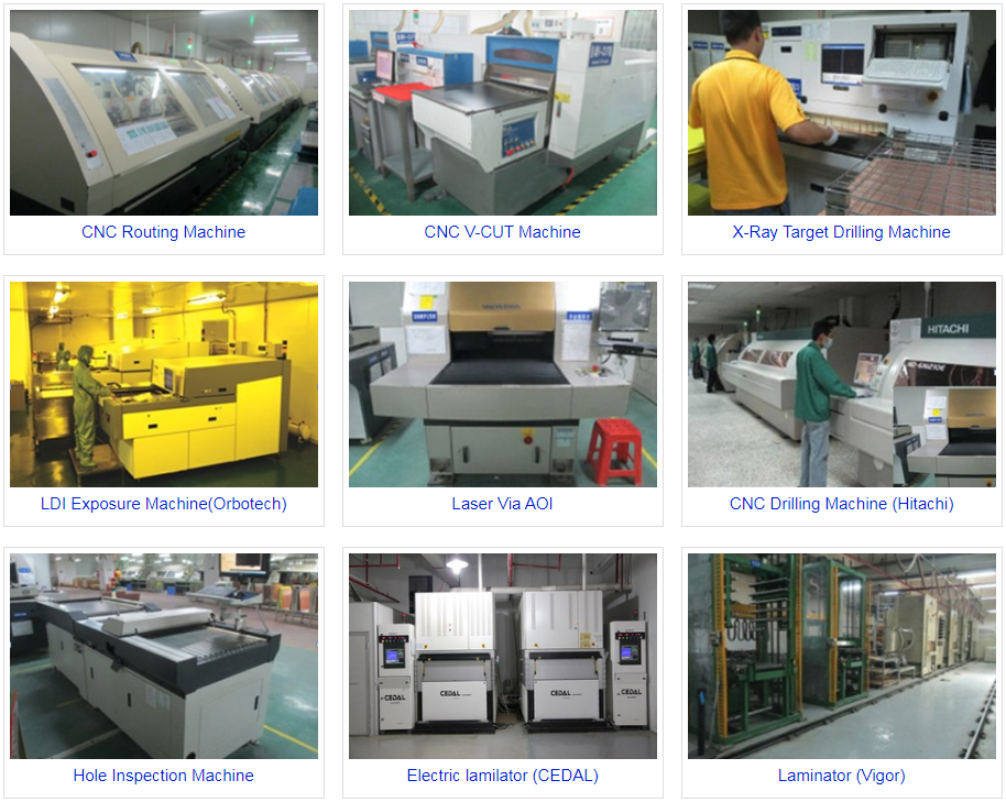
Main Equipments