Recognizing diodes and detecting their characteristics is an essential skill for anyone working with electronics. Diodes are semiconductor devices that allow current to flow in one direction while blocking it in the other, and they come in various types. Here are some key skills and methods for recognizing and detecting diodes:
- Visual Inspection:
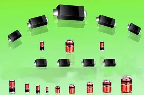
- The most basic method for identifying diodes is visual inspection. Diodes typically have a distinctive cylindrical or rectangular shape with two leads. The color of the diode and any markings on its body can provide clues to its type and characteristics.
- Reading Markings:
- Diodes often have markings that provide information about their specifications. These markings may include the part number, manufacturer’s logo, and anode/cathode identification. Carefully examine these markings and refer to datasheets for decoding.
- Color Identification:
- Some diodes are color-coded to indicate their type. For example, small signal silicon diodes are often black, while red or green glass diodes may indicate a different type.
- Using a Multimeter:
- A multimeter can be used to test diodes. In diode test mode, a multimeter can determine the forward voltage drop and reverse leakage of a diode. A good diode will typically have a forward voltage drop of about 0.6 to 0.7 volts (for silicon diodes) when the red lead of the multimeter is connected to the anode and the black lead to the cathode.
- Reverse Bias Test:
- In a reverse bias test, you can use a voltage source and a current-limiting resistor to apply a reverse voltage to the diode. This can help you identify if the diode is working correctly and has a high reverse breakdown voltage.
- Forward Bias Test:
- In a forward bias test, you can apply a small forward voltage to the diode (typically less than its forward voltage drop) and measure the resulting current. This can help you confirm that the diode conducts in the forward direction.
- Using a Curve Tracer:
- A curve tracer is a specialized test instrument that can provide detailed graphical representations of a diode’s electrical characteristics. It’s useful for in-depth analysis of diode behavior.
- Reading Datasheets:
- Datasheets from diode manufacturers provide detailed information about a diode’s electrical characteristics, including its voltage and current ratings, forward voltage drop, reverse breakdown voltage, and more. Understanding datasheets is crucial for proper diode selection and usage.
- In-Circuit Testing:
- Diodes can be tested in-circuit as part of a larger electronic circuit. In-circuit testing can help identify issues like shorted or open diodes.
- Using Semiconductor Testers:
- Semiconductor testers or diode testers are specialized instruments designed to identify and test diodes quickly. They often have features for automatic identification and measurement.
Remember that diodes come in various types, including rectifier diodes, Zener diodes, light-emitting diodes (LEDs), Schottky diodes, and more, each with specific characteristics and applications. Knowing how to recognize and test diodes is crucial for diagnosing issues and ensuring proper operation in electronic circuit boards.